As a large scale thermoplastic composite 3D printing company, CEAD strives to revolutionize the possibilities of additive manufacturing. Central in this strive for innovation are, among others, increasing both the thermoplastic output per hour and the accuracy of our large scale 3D printers.
In order to increase output, CEAD has developed groundbreaking pellet extruders and continues to do so. The aspect of increasing printing accuracy requires a different approach. This article elaborates on CEAD’s use of our laser tracker from FARO Technologies.
![]()
Accurately measuring robot based additive manufacturing set-ups
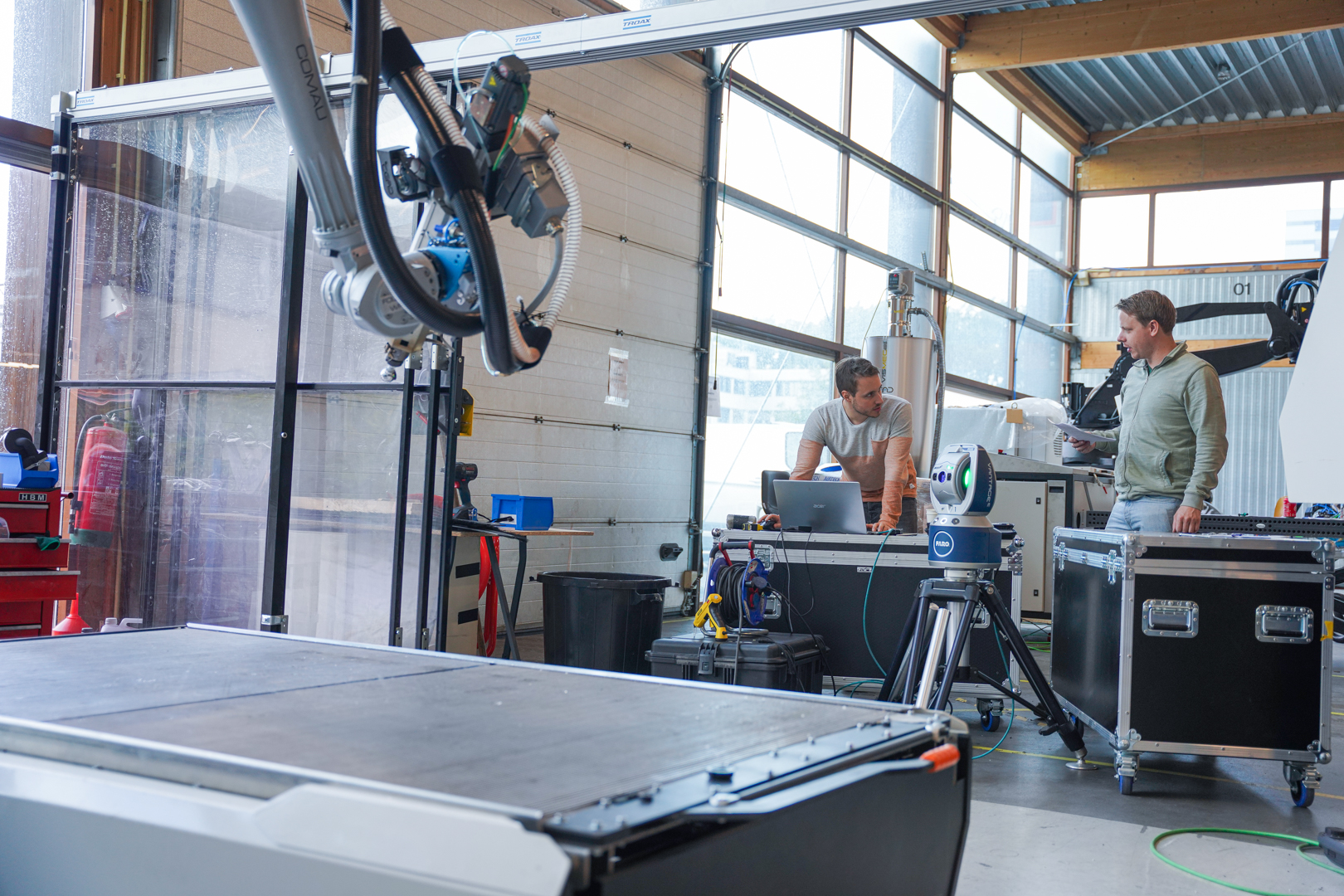
Our laser tracker is used to accurately measure our robot based large scale additive manufacturing set-ups, as can be seen in the photo above. This input is used during the robot calibration. Robot calibration refers to the process of identifying certain parameters in the kinematic structure of our 3D printing robot. An example of these parameters can be found in the relative position of the robot arm.
Because of the calibration that can be achieved thanks to the laser tracker, we are able to increase the accuracy of the 3D printing robot up to a factor of 10. This highlights the importance of calibration when using robots and linear tracks for large scale 3D printing or milling operations. By measuring with the laser tracker, we are able to achieve the accuracy required.
The laser tracker enables easy and fast on-site measurement. It measures 3D coordinates by the swivel head which tracks a reflecting target that is moved from one point to another on the object being measured. This enables fast and accurate measuring of both ABC and XYZ positions in the 3D space. These measurements can be compared against nominal CAD data, enabling us to calibrate various components of our set-ups.
Applications of measuring additive manufacturing set-ups
Our robot based additive manufacturing set-ups consist of multiple components which require additional calibration. The following paragraphs highlight the diverse usage of our laser tracker when measuring and calibrating our large scale 3D printing set-ups.
1. Calibration of linear tracks
The first application of our laser tracker is focused on accurately constructing linear tracks along which our Flexbot moves while printing. The laser tracker allows us to position the rail very accurately on threaded rods to the ground by making small adjustments based on the laser tracker readings. By doing so, we are able to level the track to a hundredth of a millimeter. This results in increased accuracy of the robot moving along the linear tracks. Improving this accuracy thus increases the stability of the extruder at the end of the robot arm.
We can verify these improvements and provide a measurement report after the installation of the Flexbot for the customer. 
2. Calibration of robot arm inaccuracies
The second application of our laser tracker can be found in kinematic calibration. The Flexbot’s robot arm consists of several pivot points. A specific motor is located at each pivot point, controlling the movements of the robot arm. Siemens NX, the slicing software, specifies where the robot arm moves along the XYZ and ABC axes.
For a 6-axis robot, such as the Flexbot, there are 24 possible deviations caused by manufacturing imperfections. These inaccuracies are affecting the final position of the extruder / milling spindle. These deviations can be in terms of different arm lengths than are specified, or rotations in the 6 rotating axes. CEAD is capable of calibrating most of these deviations by inhouse developed software algorithms combined with the use of >200 measures points in the working area of the robot.
In order to correct these deviations, the laser printer is kinematically calibrated through the measurement of >200 points in a 3D space. This measurement is used to determine the final deviations, resulting in correction values. The difference in accuracy after calibration can be up to a factor of 10, consisting of both improvements of repeatability as well as accuracy.
The repeatability of a robot is defined as the ability to achieve repetition on the same task. Accuracy on the other hand can be found in the difference between the requested task and task performed by the robot. We measure these improvements based on evaluations about the performed path, position and orientation of the robot.

3. Calibration of sag
The third and final application of calibration by the laser tracker corrects the sag of the robot arm. Sag refers to deflection caused by gravitational forces. A robot bends depending on both the weight that is hanging on the robot arm as well as the distance that the extends. The heavier the head and the further the extends, the more the accuracy suffers from sag.
It is not possible to overcome sag with kinematic calibration. However, we can apply compensation for this sag. We have written software for the calibration of sag. By doing so, we measure about 300 points in the working area. This measurement allows us to determine the exact sag, as well as the required correction to compensation for that sag.
Additional information on calibration
CEAD is proud of the unique solutions that are developed to increase the accuracy of our large scale printing solutions. We are happy to inform you about the possibilities of the laser tracker and our machines. Please feel free to contact our specialists for additional information.
Continue reading on large format additive manufacturing
Three groundbreaking world conquerors nominated for 39th edition Rotterdam Entrepreneur Award
This article was originally written in Dutch, click to read the original version in DutchCEAD,Van Donge & De Roo and Hollandia Services are the finalists of the Rotterdam Entrepreneur Award 2024. The nominees for the [...]
What staff do you need for large format additive manufacturing (LFAM)?
When it comes to implementing a new technology, involving employees during the adoption process is essential. While our large format 3D printing solutions focus on automation, people are still a crucial element. With new [...]
3D Printing in boat manufacturing
In recent years, the Netherlands has become one of the trailblazers in maritime technology, specifically with its adoption of large format 3D printing in boat manufacturing. This innovative approach to shipbuilding transforms the traditional [...]
CEAD and ADAXIS Integration Redefines Efficiency in Robotic Large Format 3D Printing
JEC World Paris, 5th March, 2024 - CEAD, frontrunner in robotic large format 3D printing solutions, is thrilled to announce a pivotal collaboration with ADAXIS, a rapidly fast-growing robotics software company. This strategic partnership aims to strengthen [...]
Large format 3D printing with PIPG
If you are looking for a cost-effective, easy to use and beautiful printing material for your large format 3D printer, PIPG is the right material. PIPG, or Post-Industrial PET-G, is an innovative recycled material [...]
3D printing with pellet extruders versus with filament
In all processes of industrial manufacturing, efficiency is key, and speed is paramount. Industrial 3D printing helps companies to improve and speed up their manufacturing processes by rapid prototyping, unlocking fast customization and by [...]
