The right driver makes the difference in realizing the full potential of our robot solution for 3D printing, the Flexbot. This is why the usage of the Flexbot is supported through Siemens NX. This software is a flexible and powerful integrated solution that helps to deliver products faster and more efficiently. The combination of Siemens NX and the Flexbot enable you to design, simulate, 3D print and mill with ease.
This article highlights the various possibilities of Siemens NX and the CEAD Flexbot. Continue reading to find out more, visit the Flexbot page or download the Flexbot brochure right away
1. Advanced slicing operations
Within the CAM Environment of NX, there are many types of Multi-Axis Deposition operations available to suit every AM need. The image on the right shows a few examples. Siemens NX allows you to slice layers with zigzag infill, print rotary layers on top of another (3D Printed or Milled) part, print single curves (for extrusion welding your prints together) and print helical tubes.
These are all relatively simple operations, but with some clever modeling tricks (which are easy to do in the NX CAD package) they allow us to make very complex parts with:
- Ribs for stiffness;
- Sufficient bead thickness for milling everywhere on the surface;
- Round edges where possible to generate a smooth toolpath;
- Nonplanar features, since you can slice in any vector.
“Designing for large-scale 3D printing” is a big topic during our operator training. During this training, we teach you everything you need to know to get started. The training is based on years of experience with our own R&D robotic AM systems.
With help from Siemens we are also working to add custom operations in the future, which result from our internal application R&D work. This makes the 3D printing process even better and easier for the operator. Our application development team is researching topics such as minimizing travel moves with advanced tool path generation, thermal optimization of the beads during layers and travel moves with just single screw extruders.


2. Bead modeling
To know exactly how much offset you need to design and program for, and how much milling stock there will be after printing, the beads can be modeled accurately. We have translated the formula into rules of thumb which can be easily used with the options in NX.
With the bead modeling capabilities, you can also simulate where and when extrusion will stop or start during prints and you can even generate the entire print and save it as a (STEP, STL, etc) model for use in other CAD packages. You can use this bead model for an accurate milling simulation, to see if your design and slicing process has been done correctly.

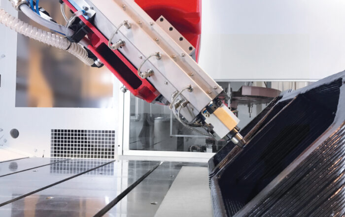
3. Advanced milling operations
Combining additive and subtractive techniques is where the Flexbot really shines. With NX you have all the tools to combine printing and milling operations into single programs, with tool changes in between. Since NX CAM for milling has been around for decades, the capabilities are endless.
We have modeled our tool changing stations and the respective moves so you can see exactly what the robot will do during the tool change. The tool library is easy to use and you can add new tools in the NX CAM environment and in the robot controller in just a few moments. The correct tool length offsets will then be automatically selected so this opens up a lot of possibilities for multi-tool programs.
Switching between the extruder and the milling spindle during a program is also possible, and you can even print first, then mill a flat spot and print again on that surface. These things can all be done without measuring a single Workpiece coordinate system because everything is combined on one machine with one work offset. This makes it very convenient to make quick plastic parts which need holes, pockets or flat surfaces in them. This is in our vision the true strength of additive manufacturing.
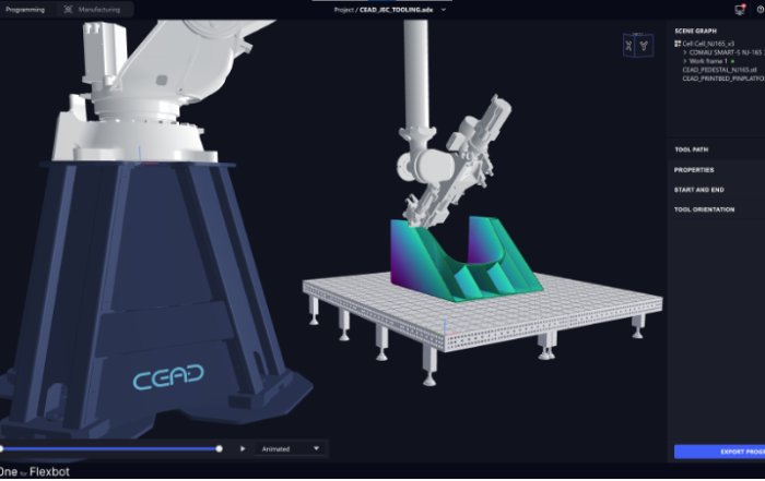
4. Simulation
Simulation is one of the biggest advantages of using a CAM package where the kinematics of the robot and end effectors are exactly modeled. There are multiple ways to check and validate toolpaths for collisions.
First off, it is possible to display the tool path and how the robot moves over it with the current device. Furthermore, you can validate the toolpath, so the software prevents possible collisions. These two methods are great for a quick analysis, and the more experienced operator might already know enough by now.
Should you need more information about the robot and its movements (which is often the case), you can not only display but also simulate the toolpath. During the simulation you can see any collisions in real time and it generates a small report after the simulation. There is one more capability after that which is to simulate the controller.
This is called CSE (Common Simulation Engine) simulation and this works by post-processing the gcode in real time while the simulation is running. The post-processed code is run on a virtual copy of your Flexbot, so the moves and rotations, accelerations and decelerations and subcycles running in the background will be exactly as in real life.
The real benefit of the simulation system of NX is that based on the operator’s experience and judgement and in different situations, different methods can be used.

5. Training
During a two-day NX training program (supplementary to the Flexbot training), our application and customer support engineers will provide an in-depth overview of the hybrid manufacturing capabilities of NX and how to use them properly.
It contains explanations and a combination of theoretical and practical exercises to get you going as soon as possible. Included are design guidelines to design for AM, how to use them in NX operations and of course we will touch on some advanced milling operations.
6. CAD modeling
The CAD modeling environment of Siemens NX enables you to create any part with ease. The dynamic sketcher is fast and intuitive to use. Additionally, any possible command is available by using the search function.
Especially for 3D printing, the synchronous modeling features are extremely useful. Synchronous modeling allows manipulation of solid bodies without a need for a history or feature tree. Solid geometry imported from a Step, IGES, Parasolid, or another CAD system can be manipulated using commands like Move Hole, Delete Feature, and Offset Face. This allows you to remove for example fillets and chamfers, and relocate faces to increase or decrease dimensions.
The main reason to use the CAD package of NX together with the CAM package is the seamless integration between the two environments. When you have a part loaded into a CAM setup, any manipulation is immediately processed in your slicing or milling operations. You can also link CAD bodies in the CAM environment so you can make small changes without altering the original part. For 3D printing and milling these are features you don’t want to miss out on.

Licensing and installation
CEAD is a partner of Siemens, not a reseller of the NX Software. In order to obtain a Siemens NX license, you are advised to buy licenses for the software from a separate reseller. We are happy to bring you into contact with your local reseller.
Typically, NX will be installed by the reseller from which you purchased the license. If support is needed with the installation, a software engineer from CEAD can be made available to assist.
The CEAD environment (machine kit) installation is a relatively easy process and is explained in the Installation manual which you will receive. The manual allows you to walk through the installation yourself. However, it is no problem to schedule a call to assist with the installation.
Continue reading on large format additive manufacturing

Three groundbreaking world conquerors nominated for 39th edition Rotterdam Entrepreneur Award
This article was originally written in Dutch, click to read the original version in DutchCEAD,Van Donge & De Roo and Hollandia Services are the finalists of the Rotterdam Entrepreneur Award 2024. The nominees for the [...]

What staff do you need for large format additive manufacturing (LFAM)?
When it comes to implementing a new technology, involving employees during the adoption process is essential. While our large format 3D printing solutions focus on automation, people are still a crucial element. With new [...]
3D Printing in boat manufacturing
In recent years, the Netherlands has become one of the trailblazers in maritime technology, specifically with its adoption of large format 3D printing in boat manufacturing. This innovative approach to shipbuilding transforms the traditional [...]
CEAD and ADAXIS Integration Redefines Efficiency in Robotic Large Format 3D Printing
JEC World Paris, 5th March, 2024 - CEAD, frontrunner in robotic large format 3D printing solutions, is thrilled to announce a pivotal collaboration with ADAXIS, a rapidly fast-growing robotics software company. This strategic partnership aims to strengthen [...]

Large format 3D printing with PIPG
If you are looking for a cost-effective, easy to use and beautiful printing material for your large format 3D printer, PIPG is the right material. PIPG, or Post-Industrial PET-G, is an innovative recycled material [...]
3D printing with pellet extruders versus with filament
In all processes of industrial manufacturing, efficiency is key, and speed is paramount. Industrial 3D printing helps companies to improve and speed up their manufacturing processes by rapid prototyping, unlocking fast customization and by [...]